Time for a new project and a new toy. This toy is a fidget toy consisting of eight cubes connected via hinges. The idea and plan come from Mitxela.com. The author has a great website including a forum, where I was able to post a question about the CAD drawing. The author answered within 24 hours!
The first step is preparing the cubes: rough cutting from stock, milling to size, and chamfering all edges. A 12" length of brass 3/4" square stock was purchased. Eight lengths were cut from this bar stock slightly longer than 3/4" using the bandsaw.

Each of these proto-cubes were held on parallels in the mill vise. One of the sawn sides was milled flat with the two insert end mill. These half-milled cubes were paired up by length, held on parallels and milled to 0.750". The three photos document the process


A jig for the mitered edges was recommended, so that was the next order of business. A block of aluminum was located that is 3/4" thick. A number of attempts were made to hold the block on the angle plate. One was finally found to be functional. It is seen in the photo below. Quite the risky setup! The end mill was aligned at what would become the top of the 45° groove. It was lowered 0.010" for each pass initially. About halfway through this was decreased to 0.0075" per pass. With a slow speed of rotation there was not much chatter. It took many passes to get to 0.35" deep. The block with the completed groove cut is shown in the second photo below.


The next step was creating the opening for the end mill. The end of the jig was marked out such that a 3/8" hole would be close to the bottom of the V-groove. The punched mark was center drilled, drilled with a 1/4" drill and then a 5/16" drill. The hole was opened to 3/8" with a four flute end mill. The back side of the hole was opened with the end mill in 0.020" passes and went smoothly. The end mill was aligned with the front of the hole and moved forward 0.020". It was lowered to the bottom of the hole. A couple of repetitions and a tiny hole was opened in the bottom of the V-groove.

The cubes were pushed by the end mill by hand. This was extremely difficult as there was tremendous chatter at a couple of different speeds. The resulting chamfers are some of the worst I have seen. Admittedly, it was a quick operation to chamfer all 96 edges.

The cubes were all marked for hinge locations. Two sets of four were made with the set members being mirror images of the opposite set. This is more easily seen in the photo below than described.

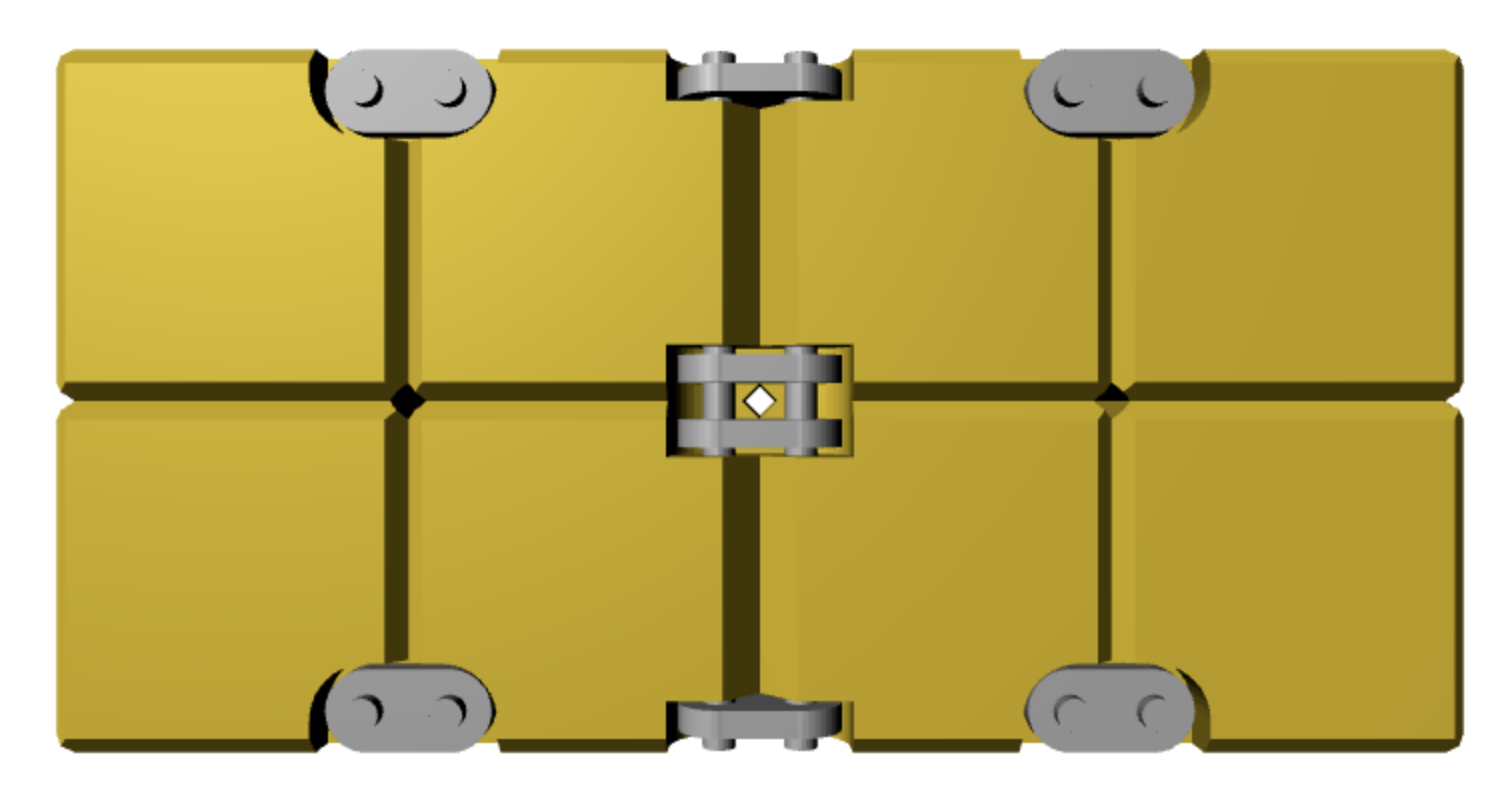
Hinges are next on the to-do list. Based on a few measurements taken from the CAD drawing on the Mitxela website a rough guess at relevant dimensions for the hinges is as follows: distance between pins is 3/16", length of the linkages is 3/8", thickness of the linkages is 1/16", and linkage width is 1/8". There is essentially no gap between cubes when the linkage is closed. The hinge cutouts look to be 1/8" deep and 1/32" beyond the linkage. The hinge cutouts in the cube corners need to be 1/8" deep and 3/16" in each direction. (Really only 7/32" in one direction, along the linkage axis, but easier to keep both dimensions identical.) A #51 drill (0.067") will be used for the hinge pin holes. 3/4" hinge pins will provide the needed 1/16" at each end for peening.
The edges marked out with the Sharpie above need a larger chamfer to permit easier hinge movement. For clarity sake the cutouts for the hinges are on the ends of these edges.
Increasing the chamfer on two marked edges per cube was the first order of business this morning. This was not done with the jig described above, but by holding two cubes on parallels in the mill vise and using a chamfering end mill. This worked so well that the rest of the edges were chamfered again. (At least the edges that were not already chamfered too deeply to clean up.) The two photos below show the larger chamfers and the cubes after chamfering all edges.


Milling the hinge pockets was done with the mill vise using a machinist's clamp as a stop. The corner was located with the edge finder. A 3/16" end mill was set 3/16" into the cube on the y-axis. The end mill was advanced on the x-axis 0.188" in 0.010" increments. The end mill was advanced on the y-axis out of the pocket as the last cutting operation. The photo below shows the result of the first pocket milling operation.

The second and adjacent pocket was milled next and took about seven minutes including setup. The pockets need to be deburred prior to milling the second pocket of the pair. Four cubes, sixteen pockets were milled before taking a break. The remainder were finished the next day. There were two mistakes on one hinge location, where I screwed up the direction of milling, the spindle axis needs to align with the eventual pin axis. These mistakes were repaired as much as possible. Hopefully the hinge will hide most of the damage, or else the cube will need to be remade. The photo below shows the eight cubes with four hinge pockets milled in each.

The setup for drilling the cubes was similar to that for milling the pockets. The cube was pressed against a clamp stop in the mill vise. The corner to be drilled was located adjacent to the clamp and the back of the vise. The edges were located and the spindle moved 3/32" in from each edge. Each hole was started with a center drill and continued through with a #51 drill, 0.067". After the first 0.150 - 0.200" the drill was pulled from the hole and cleaned of chips every 0.050". The burrs on the hole exit were removed with the center drill. A drilled cube is shown below.

When drilling the first hole looking at the drill as it was about half-way through, I thought the drill was going off track. This was a warning and I then was very careful to remove chips often. As more holes were drilled I realized when I put my head down to look at the drill from the side, it always looked crooked. How I love my astigmatism!
I am worried about the cube with the two bungled pockets. The hole was drilled between them and the center drill had to drill out some of the ledge in the corner as it entered the flat. The flat is not at the same height as the other holes and is has ledges on both sides. I am not sure the hinge will sit well enough to function. I have one cube that is 0.753" from cut face to cut face. We will see if milling the cut faces flat and square will leave it too short for use. After milling both sides the cube is about 0.012" shorter in one dimension. This should be acceptable.
The cube was set up against the stop and the four pockets were milled with care taken to make sure it was the same enantiomer (handedness) as the one it replaces. The holes were drilled as before. The edges were all chamfered with the two edges along the hinges chamfered deeper. The eight cubes are complete.
The links or hinge pin connectors will be made next. They will be 3/8" long and 1/8" wide. The two holes will be 3/16" apart. The plan is to begin with strips of 1/16" stainless steel, drill the holes and cut to separate links. Sanding, using a jig, will reduce all to the final shape and dimensions.
The first order of business is cutting 8" of 3/16" wide stainless steel strips. The 410 stainless steel is left over from the pen project, almost a square foot remains.
Dykem was painted on one edge of the stainless steel sheet. A caliper was used to scratch a line at 3/16" along the edge. The hacksaw was used to cut along this line. The first picture shows the cutting in progress. The second shows the two cut strips.


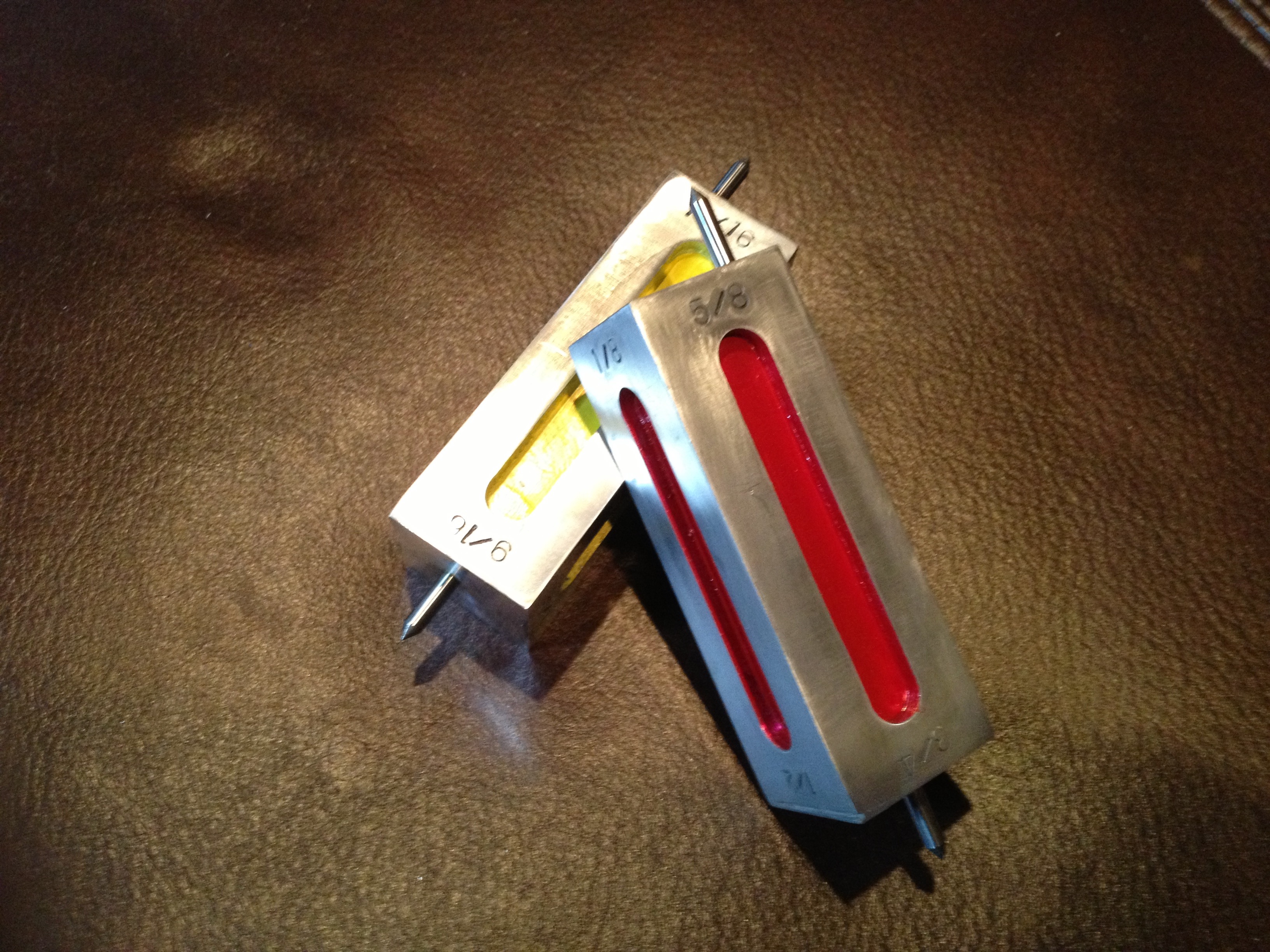
The two strips were marked out using a combination of 1-2-3 blocks and the height marking blocks made long ago (shown below). The marks were made every 3/8". The second photo shows the marked out strips.

After returning from a week with family in Puerto Vallarta, I started the sanding needed to narrow these strips to 1/8". Oy!! The old 80 grit belt on the sander was almost smooth. A new belt was installed, but it is only 120 grit. The parts can only be held on the belt for 10-15 seconds before they get too hot, even twhen held with pliers. The sanding is very slow and at least an 1/8" has to be removed. I need to trust my hacksawing more.
Significant sanding later and water cooling every fifteen seconds both strips of stainless steel are now 1/8" wide. The long strip was clamped to a piece of wood with two clamps and held in the vise. The center drill left only a small mark. The steel had hardened during the sanding! Back to the hacksaw.
Two 6" long strips of stainless steel were cut from the sheet 3/16" wide. Both were deburred. One was sufficient for the sixteen parts. One strip was affixed to a long strip of Baltic birch plywood using carpet tape. This was held on parallels in the mill vise. The spindle was centered over the end of steel strip and advanced about 0.08", a bit over the 1/16" needed. A hole was center drilled and then drilled through with a #51 drill.
The table was advanced 0.188" and the drilling was repeated. After about fifteen holes (all 0.188" apart) the #51 drill started complaining. It was easily replaced from the drill stash in the garage with a sharp one. The remainder of the holes went smoothly, though boring. The strip was long enough for the required sixteen parts and one extra, 34 holes. The photo below shows the strip in the middle of the drilling process.

The steel strip still attached to the strip of plywood was held in the shop vise. A C-clamp held the strip more firmly in place and a cut was made between parts with a hacksaw. The strip was shifted in the vise and the C-clamp moved close to the cut for each successive cut. At the end of cutting the part there were only sixteen parts; not sure where the extra went. The drilled holes were deburred with a file. This took as long as cutting them apart. The first photo below shows the cutting setup and the second shows the deburred parts ready for sanding to shape.


A jig was made for sanding the links to the appropriate width. A notch was cut in the previously used and now shortened strip of Baltic birch plywood. An aluminum scrap fit in the notch and sits flat on the sanding table, when the wood strip rides in the table's track. The end of the aluminum was sanded flush when the jig was in the track. The end was then drilled for two holes, 3/16" apart and 1/16" in from the sanded edge. The holes were drilled with the #51 drill and two #0-80 screws were used with nuts to serve as pins for holding the links. A link was placed on the jig and the jig was pressed tight to the front edge of the track, the wood is narrower than the track it rides in, sanding off one side of the link. The sanding disk is 120 grit. The first photo shows the jig and the second shows the jig in use.


After successfully narrowing all of the links to 1/8" the jig was converted to a corner rounding jig. One screw was removed. A strip of brass was drilled with a #50 drill 1/16" in from the end. A second hole was drilled 3/16" further in. A 0-80 screw was put through the hole in the brass strip and locked in place with a nut. The strip was placed over the pivot screw in the jig body and held loosely with a nut. The revamped jig was placed on the table and the strip's end was sanded round. A link was placed on the two screws, the jig held on the table, and the strip was rotated first in one direction and then in the other, rounding over both corners of one end. Flipping and repeating turned the rectangular links into ovals. The first photo shows the modified jig, the second shows it in use and the third shows the pile of oval links.


The links require sanding and polishing after the rather intense heat from the sanding. Most have turned an interesting shade of tan from the heat. Both sides of each link were sanded with 600 grit sandpaper. Further sanding with 1000 and 2000 grit made little observable difference, so sanding was stopped at 600. The photo shows a pile of sanded links. I couldn't resist linking two blocks and the second photo shows them held in place with screws dropped through. The 0-80 screws are not long enough to use them with nuts. There is decent play between the blocks.


In fact what am I going to use as the rods between links? I can't believe I have not thought of this until now. The smallest rod I have is 3/32" brass. I don't want to peen thirty-two rod ends, so am exploring machine screws. I can purchase 3/4" thread length screws, but that is probably 1/16" too long necessitating lathe shortening. Either locknuts or thread locker should hold the nuts without hindering movement.
Another concern is weight. Mitxela indicates that the set of cubes is pretty heavy for a handheld toy. Holding all of the cubes in one hand confirms this opinion. One possibility is drilling all six faces of each cube with a 3/8" drill to a 1/8" depth. This would reduce the volume of the cube by 20%, probably not sufficient for the effort. Drilling through from two directions with a 3/8" drill would reduce the weight by a third.
The screws were ordered this morning, #0-80 X 3/4". Meanwhile, cube weight reductions were explored. The extra damaged cube was centered in the four-jaw chuck to within 0.001". It was center drilled, drilled with a #6 drill, followed by a 9/32" drill, and then a 3/8" drill. The weight was reduced from 55 g to 43 g, per calculations. Second and then third orthogonal holes were drilled. With only two the cube looked unfinished. The holes were lightly chamfered with the hand-held tool. The first photo below shows the drilling setup and the second photo the thrice drilled cube.


The drilled cube weighed in at 28 g! So instead of the entire toy weighing almost one pound it will now weigh half of a pound.
A few different sanding protocols were explored on the extra cube. 400 grit was followed by 600 grit to give a matte appearance. 1000 and 2000 grit were then used and the polish was good, but not great. All unsanded faces were sanded to 600 and then all faces were polished on the buffing wheel with red rouge. This produced a nice shine as expected.
Two modifications need to be incorporated while drilling. First, the holes should be reamed to 3/8". This will give a much nicer finish on the internal surfaces. Second, the part needs to be held in the chuck with a parallel or spider behind it. The machined corners can allow the part to twist in the chuck. This was noticed when chamfering the holes.
The first of the blocks was placed in the chuck over a spider. All three holes were drilled, reamed, and chamfered. This was repeated for the rest of the blocks. About twenty minutes per block, but they were completed and look good as shown in the photo below. They are also significantly lighter as planned.

Began the hand sanding by sanding all 48 sides with 400 grit sandpaper. The sanding was continued with 600 grit paper. A Sharpie dot was put on each side to more easily distinguish which sides had not been sanded. The next step was polishing all with red rouge on the buffing wheel. The photo below shows the halfway point in polishing. The remainder were buffed and all checked and in some cases rebuffed.

Spent about three hours cleaning the cubes of the buffing residue. First they were rinsed with an aqueous solution of NaHCO3 and then scrubbed with soap and water. A towel and a pipe cleaner were used to clean all of the openings. There was significant residue in the 3/8" drilled holes to remove. After a second wash with soapy water the cubes were rinsed with water and then with acetone. Gloves were worn from this point on.
The faces and bevels of the cubes were painted with Protecta-Clear varnish. They were hung on a copper wire held in the vise to dry. They were recoated after an intermediate 45 minute drying period. The brush was cleaned after each use with lacquer thinner. (Xylene is recommended for cleaning.) The photo below shows the cubes after the first coat of varnish. The second coat dried for 24 hours before the cubes were taken down from the wire. The second photo shows the completed cubes and links. Now I just have to wait patiently for the screws to arrive allowing assembly and more importantly fiddling with the assembled toy.


The screws finally arrived on the seventeenth. I immediately began shortening them. They need to be shortened by about 1/16". The lathe screw holder was tried first. The screw did not run true. After a few other unsuccessful attempts via different methods, the following method was adopted. Two nuts are threaded onto the screw and tightened together. A 0-80 die is threaded onto the screw. The screw is held in the vise via the two nuts with the die pressed tight against the side of the jaws. The screw is cut with a hacksaw. Removing the die cleans up the threads! The process is slow, mostly because it is so difficult to work with such small parts in my fat and clumsy fingers. The job will need to be finished tomorrow morning, when I am raring to go. Below is a photo of a successfully assembled linkage, probably not a correct pairing.

The screws were tackled this morning, while listening to some jazz fusion. The distraction was a necessity. Each screw had two nuts put on and locked together. Then the 0-80 die was put on with the labeled side toward the end to be cut. About 1/8" of screw protruded from the die. The whole thing was put in the vise with the die flat against the side of the jaws. About 1/16" was cut off with the hacksaw. After removing the die the nuts were usually trivial to remove. Many screws later the job was done. Below is a photo of a screw ready for cutting.

Test assembly was next. First the cubes were sorted into the two groups of enantiomers. The cubes were then set up in the correct fashion for attaching per a diagram I had sketched. The cubes were assembled into pairs first as seen in the first photo below. Then the pairs were attached. One link needed to be filed so it would move freely. One link did not seem to have sufficient spacing between the two holes, but I was able to make it work. Holding cubes, screws, links and attaching nuts was quite the challenge for my clumsy fingers. Eventually the eight cubes were attached as shown in the second and third photos below. Glueing the nuts in place will be tackled at a future date.
The later date was today, three days later. It took 1 1/2 hours to put the blocks back together with a drop of blue Loctite in each tiny nut. A dental pick was used to apply the tiny drop of glue. The glue requires 24 hours to completely dry.


